Plinth, Part 1Many questions arose when I tried to start building the turntable: how big should the plinth be? What materials should I use to make the plinth? Should the plinth incorporate a suspension system? Should the platter-drive motor be mounted on the plinth or on a separate box? What the heck is a plinth?
Starting with the last question, John Parker said, “A plinth is the enclosure or stand used to support your platter and bearing assembly. This will be the foundation of your design. Please remember that the plinth design will need to be executed in such a way as to offer complete stability. Stability can be achieved through a build that offers both weight and precise construction. If the plinth is not stable and level, the entire project will suffer.”
After struggling to choose a direction, I realized I had to start somewhere that might not have the optimal solutio, but would give me a starting point for future comparisons. I decided to make the plinth out of layers of birch-veneered plywood. A suspension system was too complicated to consider, so I skipped it and hoped that I could isolate the turntable in other ways. The platter was designed for belt drive around its perimeter, and John Parker said, “If you mount the motor and drive pulley very close to the platter, then you will need to consider the reduced wrap angle of the belting material and the reduced surface area that can be used to retain tension on the belting material. This could cause very irregular speed control because of slippage.” For this reason, the motor was mounted in its own box separate from the plinth.
How did I answer the question of how big to make the plinth? Well, it should probably be bigger than the platter and tonearm, but not so much that I couln’t fit it on a shelf. An interesting source online at
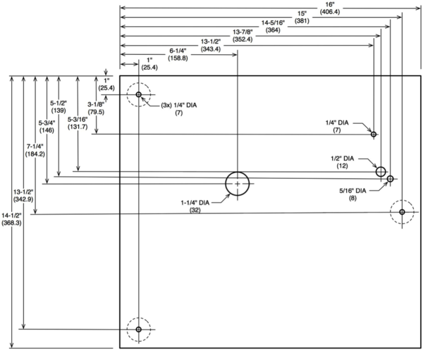
http://www.vinylengine.com/tonearm_database.php described mounting requirements for many commercial arms, and I started to find a plinth size that would support as many arms as possible. Then I realized that I probably wouldn’t change the tonearm anyway, so I just made the plinth big enough for the Lin tonearm. In the end, I made the plinth 16” wide and 14½” deep, as shown in Figure 6. These dimensions increased by 1½“ when the plywood plinth was wrapped with ¾“ oak.
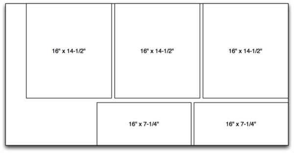
I chose birch-veneer plywood because it was available, had more plies and less voids than regular plywood, and provided a finished surface when assembled. Voids could cause resonant cavities in the plinth, and should be avoided (so to speak). By using a 2’ x 4’ sheet of plywood, I could get all my pieces with at least one manufactured edge to allow square trimming later, as long as I didn’t mind joining two pieces to make the bottom layer. See Figure 4 for a cutting plan.
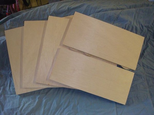
Figure 5 shows the five pieces of plywood cut to size. The two narrow pieces were slotted for gluing biscuits and glued together, giving me four equal-size pieces. The fourth biscuit was missing because the section of seam it would occupy was cut out to provide access to the bearing’s torque nut.
I drilled the two top pieces to receive the bearing, which was designed for a 1½“ plate. I put blue painters’ tape on the wood and marked my layout lines on the tape so I wouldn’t have to sand off the layout lines later, and the tape reduced splintering when sawing and drilling. Before drilling the bearing hole, you should lay out the tonearm mounting holes that key off the center of the platter. The tonearm came with laminated templates that are harder to use once you replace the bearing center point with a big hole! I had to go back and cover the bearing hole with painters’ tape, locate the center again, and then locate the tonearm mounting holes.
Attachment:
File comment: Figure 4: Cutting Sheet for Plinth using 2’ x 4’ Sheet of Plywood
 Cutting Sheet for Plinth.png [ 47.53 KiB | Viewed 202850 times ]
Attachment:
File comment: Figure 5: Plywood Pieces that Make Up the Plinth
 Plywood Pieces for the Plinth.jpg [ 35.08 KiB | Viewed 202850 times ]
Attachment:
File comment: Figure 6: Dimensions of Plinth Top Plate
 Dimensions of Plinth Top Plate.png [ 202.94 KiB | Viewed 202850 times ]
I laid out the two top pieces carefully using the factory edges for reference and marked the bearing hole 5¾” from the back and 6¼“ from the left as laid out in Figure 6. I drilled the two holes separately on a drill press because it’s easier to drill thinner pieces then thicker – the bits get very hot when you drill thick stuff. I used a 1¼” hole saw because I didn’t have a Forstner bit that big, and, in my experience, a spade bit usually makes a horribly rough hole – good for rough carpentry but not for cabinetwork.
Copyright 2012 Guy W. Riffle. All rights reserved.


