DCAudioDIY.com http://www.dcaudiodiy.com/phpBB3/ |
|
Constant Current Source: Cascode DN2540 MOSFETs http://www.dcaudiodiy.com/phpBB3/viewtopic.php?f=4&t=69 |
Page 2 of 2 |
Author: | Guy [ August 25th, 2013, 4:11 pm ] |
Post subject: | Re: Constant Current Source: Cascode DN2540 MOSFETs |
The choice of 1K for gate resistors was just a seat-of-the-pants selection. I haven't tried to see how the frequency response of the circuit changes with the use of other values. Please feel free to experiment and let us know what happens! |
Author: | Guy [ August 25th, 2013, 4:40 pm ] |
Post subject: | Re: Constant Current Source: Cascode DN2540 MOSFETs |
For more information, see the following link (among others): http://www.pimmlabs.com/web/Active_load ... ntrol.html Some experimenters have experienced high-frequency oscillation in CCSs because of pickup of external radio frequencies (RF). Oscillation can be controlled by adding a small-valued resistor (R2-R9) in series with the gate of each MOSFET to filter the RF. Some experimenters jumper the gate-stopper resistors (R2-R9) and have no oscillations; those who experience oscillation use the smallest resistor they can to stop the oscillations – some use just 100 Ohms instead of the specified 1000 Ohms. The choice is up to the builder. Adjustment-Resistor Values can be estimated with this equation:
Current Output can be estimated with this equation:
The specified trimmers are for currents greater than about 1½ mA. For more adjustment of higher currents, the builder may want to substitute a lower-value trimmer resistor for U1-U4. For example, a 250-Ohm trimmer is probably good for currents over 6 mA, and a 100-Ohm trimmer is probably good for currents over 13 mA. 
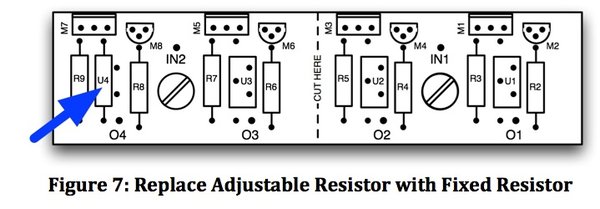
There are provisions on the PCB to replace the current-adjust resistors (U1-U4) with fixed resistors like those used for (R2-R9) once the required values are found by experiment. The builder may want to buy a single adjustable resistor to find the required value, and then buy cheaper fixed resistors for the CCSs. Populating the Board: Start by installing the TO 92 packages (M8, M6, M4, M2). The center lead must be bent away from the flat side and down to meet the center pads on the board for each part. Installing the TO 92 packages first allows better access for heat-sinking the leads while soldering. Next, install the TO 220 packages. The leads can be left straight if the heat sink is mounted perpendicular to the PCB. If the heat sink is below and parallel to the PCB, bend the leads up as shown in the earlier figure called "TO-220 Under." If the heat sink is above and parallel to the PCB, or about on the same plane as the PCB, bend the leads down as shown in the earlier figure called "TO-220 Over." Provide proper heat sinking to leads while soldering. Install the CERMET pots (U4-U1), followed by the grid-stopper resistors (R9-R2). If fixed current-adjust resistors are used, replace the pot with a fixed resistor. For example, Figure 7 shows the leftmost adjustable resistor U4 replaced by a fixed resistor. The other three CCSs have similar pads for fixed resistors. Attachment:
File comment: Replacing a TrimPot with a Fixed Resistor Fixed Resistor.jpg [ 61.76 KiB | Viewed 22848 times ] Adjusting the Circuit 
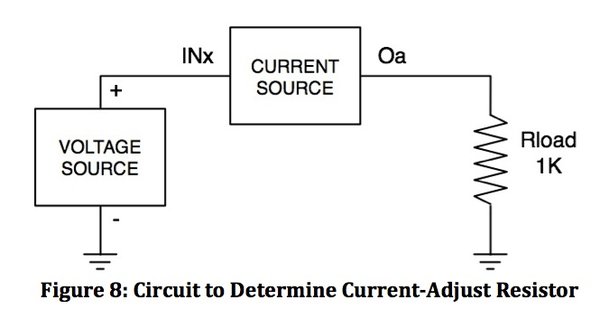
An easy way to set the current is to connect a 1KΩ resistor from one of the outputs (O1 O4) to ground, and a power source from the appropriate input (IN1, IN2) to ground as shown in the figure below. Apply at least 20V DC to the current source and adjust the appropriate current-adjust resistor to the desired current output. Measure the voltage across the load resistor (Rload). Compute the output current, which is the measured load voltage divided by the load resistance (1,000 Ohms). For example, to adjust for 30 mA, there will be 30 Volts across the load resistor and at least 20 Volts across the current source, so a minimum of 50 Volts DC is required from the power source. Other values of load resistors can be used to allow other voltages for setting the output current - just use the value of the load resistor in the equation. Attachment:
|
Author: | Guy [ February 6th, 2014, 3:11 pm ] |
Post subject: | Re: Constant Current Source: Cascode DN2540 MOSFETs |
Jetbat, Good work! You've done something I haven't done in a few months - make something that works! Please let us know how the CCSs work, especially if there are problems like smoke! I'd like to correct problems before I propagate them! |
Author: | Guy [ February 6th, 2014, 3:13 pm ] |
Post subject: | Re: Constant Current Source: Cascode DN2540 MOSFETs |
Jetbat, aren't those DN2540s getting hot without a heatsink? And you're sourcing 110 mA apiece? That's cool! (as in groovy, because they're probably thermal hot!) |
Author: | Jetbat [ February 6th, 2014, 3:34 pm ] |
Post subject: | Re: Constant Current Source: Cascode DN2540 MOSFETs |
No they are cool. There is only a five volt drop from +27V power supply to +22V regulator. The shunt transistors needed heatsinks though. |
Author: | Jetbat [ February 7th, 2014, 11:53 pm ] | ||
Post subject: | Re: Constant Current Source: Cascode DN2540 MOSFETs | ||
This is a circuit I found which seems very promising. This is the text describing it. 'Circuit C combines a JFET cascode together with a high-quality monolithic precision voltage reference. The reference IC keeps Q1's Vgs constant over a wide temperature span, to create a high-quality current source with less that 50-ppm regulation. The output current is set by the reference voltage output divided by the value of the precision resistor (a 0.1% or better tolerance and less that 50-ppm metal-film type). The addition of the voltage reference also improves overall temperature stability and boosts output impedance to about 1 GΩ.' I have experienced a noticeable difference between a single jfet CCS and a cascode CCS in sound quality. With the cascode CCS having a output impedance of >5 MΩ, the reference voltage CCS should give even better results. I will try this out and see. Scott
|
Author: | Jetbat [ February 8th, 2014, 3:50 pm ] | ||
Post subject: | Re: Constant Current Source: Cascode DN2540 MOSFETs | ||
Guy, I'm still learning here. The internet teaches me things but does not correct me when I am wrong. In trying to understand the DN2540 CCS I found this graph which helps me immensely. The graph is for a single jfet CCS but it puts things into perspective that I can apply to a cascode CCS. I now understand that while my application of this circuit works, it is no where near optimum. The 5V across CCS is too low. I need to increase that to at least 10V but 20V would give me some margin. Looking back through this thread I see you did recommend at least 20V across the CCS. Duh! So while it does work in this application, the isolation/impedance of the circuit is probably much lower than it could be. Looks like a new power transformer is in my future. Scott
|
Author: | Guy [ February 9th, 2014, 12:46 pm ] |
Post subject: | Re: Constant Current Source: Cascode DN2540 MOSFETs |
Scott, I was surprised that you had stable performance with 5V across the CCS, but why questions success? You noted improvement in channel separation and high-frequency response so I delayed in suggesting an increase in supply. Fortunately your supply is low voltage relative to an EL84 supply so the transformer shouldn't be too expensive. Heat sinks on the DN2540s may be important once the dissipation rises from 1/2 W to 2-1/4W each. I like your proposed circuit and am eager to see what you think about its sonic performance compared to the cascode-MODFET circuit. The cascode is not an extreme circuit, but has great performance given the simplicity of the circuit. I offered the PCB because it's a fast and inexpensive way to get a circuit going, and I'm gad you gave them a try! |
Page 2 of 2 | All times are UTC - 5 hours [ DST ] |
Powered by phpBB® Forum Software © phpBB Group https://www.phpbb.com/ |