Constant current sources (CCSs) provide isolation between the power supply and a circuit, and provide equivalent resistance much higher that practically available with passive parts. Here is a simple one:
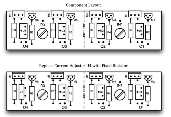
I have a printed circuit board (PCB) for four simple cascode CCSs, each using a pair of N-channel depletion-mode MOSFETs. For convenience, the board can be cut in half to provide two pairs of CCSs. The PCB is 1" x 4", and is mounted with two 6-32 screws spaced 2" apart. The MOSFETs with the highest dissipation are located at the edge of the board to make it easy to share a heat sink (
NOTE: the TO-220 tab is connected to the input high voltage, so take care around the heat sink and insulate it from the tabs.) The input and output wire pads are sized for 18 AWG wire.
Let me know if you want to buy a PCB or two!

The current adjust resistors (U1 - U4) can be replaced with fixed resistors once the desired current output is determined. An easy way to set the current is to connect a 1K resistor from the output (O1 - O4) to ground, and a power source from the input (IN1, IN2) to ground. Apply at least 20V DC to the CCS and adjust the appropriate current-adjust resistor to the desired current output. For example, to adjust for 30 mA, there ill be 30V across the load resistor and at least 20V across the CCS, so a minimum of 50V DC is required from the power source. Other load-resistor values can be used.
PARTS:
(4) U1-U4: Trimmer Resistor, 12-turn 1K sealed top adjust: Mouser 81-PV37W102C01B00, $1.25 ea, $5.00 for 4
(8) R2-R9: Stakpole Carbon Film 1/2W 2% 1K: Handmade 8-06051001, $0.10 ea, $0.80 for 8
(4) M1, M3, M5, M7: SuperTex DN2540 MOSFET 400V, 25 Ohm, TO-220: Mouser 689-DN2540N5-G, $1.60 ea, $6.40 for 4
(4) M2, M4, M6, M8: SuperTex DN2540 MOSFET 400V, 25 Ohm, TO-92: Mouser 689-DN2540N3-G, $0.87 ea, $3.48 for 4
(1) PCB: $5.00 ea
TOTAL: $20.68 for 4 CCSs.
ESTIMATED CURRENT-ADJUST RESISTORS:
Code:
|Resistor| Output |
| Value | Current|
| (Ohms) | (mA) |
| 39 | 30.1 |
| 47 | 25.6 |
| 62 | 20.1 |
| 82 | 15.7 |
| 91 | 14.2 |
| 110 | 12 |
| 150 | 9 |
| 270 | 5.1 |
| 330 | 4.25 |
| 510 | 2.8 |
Attachment:
File comment: PCB Component Side
 DSCN3013.jpg [ 663.56 KiB | Viewed 43997 times ]
Attachment:
File comment: PCB Solder Side
 DSCN3015.jpg [ 661.3 KiB | Viewed 43997 times ]
Attachment:
File comment: Component Layout
 n5WwDC.jpg [ 152.16 KiB | Viewed 43997 times ]


