Best practices
April 12th, 2022, 10:23 am
I want to rebuild the crossovers in the RAZZ. The boards I have were from a prototype that I have upgraded as changes were made like the recent inductor upgrade.
I never liked the construction techniques originally used and accepted them because it was a prototype that I purchased at a very low price.
The drivers have never changed.
It is the wiring that has me concerned.
There are four types of connections.
14ga solid copper to 14ga stranded
14ga solid copper to 14ga solid copper
14ga stranded to 14ga stranded.
The padding resistors need to be easily removable and originally the leads were just wrapped around metal screws and tightened down against a ring terminal crimped to a 14ga stranded wire to the rest of the crossover. I need to find high-quality ring terminals for the resistors and make a good quality connection to the rest of the crossover.
Re: Best practices
April 12th, 2022, 10:37 am
Pelliott321 wrote:I want to rebuild the crossovers in the RAZZ. The boards I have were from a prototype that I have upgraded as changes were made like the recent inductor upgrade.
I never liked the construction techniques originally used and accepted them because it was a prototype that I purchased at a very low price.
The drivers have never changed.
It is the wiring that has me concerned.
There are four types of connections.
14ga solid copper to 14ga stranded
14ga solid copper to 14ga solid copper
14ga stranded to 14ga stranded.
The padding resistors need to be easily removable and originally the leads were just wrapped around metal screws and tightened down against a ring terminal crimped to a 14ga stranded wire to the rest of the crossover. I need to find high-quality ring terminals for the resistors and make a good quality connection to the rest of the crossover.
There are many ways to "skin this cat." You can create your own custom PC boards, or use perforated boards, or (my favorite) use turret boards.
- Attachments
-
Re: Best practices
April 12th, 2022, 11:40 am
might work
but it would change the layout completely.
I think it would require longer leads, which I am trying to avoid.
but it would change the layout completely.
I think it would require longer leads, which I am trying to avoid.
Re: Best practices
April 12th, 2022, 12:02 pm
Pelliott321 wrote:might work
but it would change the layout completely.
I think it would require longer leads, which I am trying to avoid.
I don't think longer leads will matter much. You were talking about 14-gauge wire which only equates to about .0025-ohms/foot. You would have to have 400-foot lengths before you even reached 1-ohm.
I am much more concerned with insulation and conductor quality. Any passive crossover work I have done for myself and others I have used silver-clad copper wire with Teflon dielectric.
Re: Best practices
April 12th, 2022, 12:03 pm
Turret boards come in a wide variety of shapes and sizes... They're popular with boutique guitar amp manufacturers, so places that sell parts to those guys are good places to look. I would not recommend doing you own PC boards unless you're fairly sure the crossover isn't going to change in the future, PC board traces don't hold up well to repeated re-soldering...
Roscoe
Roscoe
Re: Best practices
April 12th, 2022, 12:27 pm
I would definitely go point-to-point on a board material of your choice.
Use something you can easily drill through, but will be reasonably non-resonant.
Maybe some 3-4mm Polypropylene sheet?
You can run some of the conductors on the back side, if it helps with the layout.
Use something you can easily drill through, but will be reasonably non-resonant.
Maybe some 3-4mm Polypropylene sheet?
You can run some of the conductors on the back side, if it helps with the layout.
Re: Best practices
April 12th, 2022, 3:03 pm
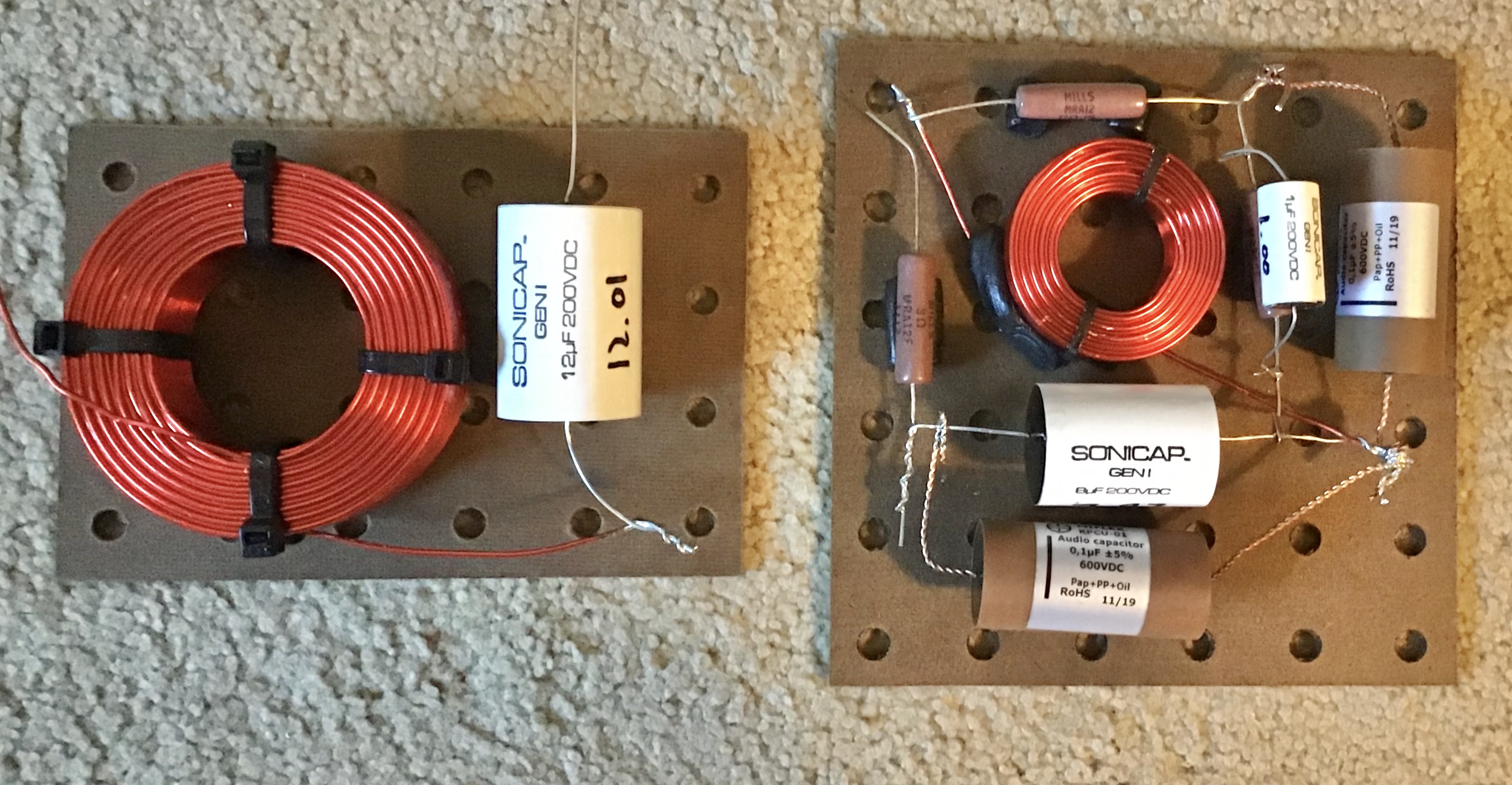
What I am asking about is how is the best way to connect two wires together.
Is twisting them together and soldering the best way, like in the above picture, or is there a better way?
Should they be crimped with a copper feral, then solder?
Is twisting them together and soldering the best way, like in the above picture, or is there a better way?
Should they be crimped with a copper feral, then solder?
Re: Best practices
April 12th, 2022, 3:38 pm
Absolutely nothing wrong with twisting & soldering as in Bruce's pic..
Roscoe
Roscoe
Re: Best practices
April 12th, 2022, 3:45 pm
Yes it will conduct a signal.
But when you twist solid copper wire you disturb the crystal structure.
not convinced this is the "best way".
But when you twist solid copper wire you disturb the crystal structure.
not convinced this is the "best way".
Re: Best practices
April 12th, 2022, 4:39 pm
Pelliott321 wrote:Yes it will conduct a signal.
But when you twist solid copper wire you disturb the crystal structure.
not convinced this is the "best way".
From my point of view I don't like any of my work to look amateurish. I don't think you do either.
If you are going to twist the wire like that for soldering than at least use a Western Union splice and then cover it with shrink tubing.
As far as disturbing the crystal structure is concerned -- that's not even an issue. ???
- Attachments
-
- 330px-Western_Union_splice.jpg (24.57 KiB) Viewed 9787 times